How the Other Track Lives:
Designing an Automated Control System for Two Trains
One of our later test runs before the final modifications of the code.
Overview
This was my final team project and final report for my MAE 412 Microprocessors course. My two partners were Joshua Umansky and Daniel Echeverri. In the first half of the course, my team designed, built and programmed a single-board microcomputer. For the second half of the course, we programmed the microcomputer to synchronize two model trains on different levels of a railroad set. The project used three hall effect sensors on each railway to find data points to predict the speed and location of both trains. Hornby Railway’s “Zero One” system in which digital data is transmitted along with power on the rails.

Orcad Schematic of the vector computer we built for the project.
This vector board mounts directly onto the project board as and connects to the
signal sensor board through the umbilical cord.

Image of the wiring behind our vector board.
Project Summary and Motivation
As a New Yorker who spent at least 2 hours on the subway system daily throughout high school, I was not a fan of the waiting time of transfers. This inspired the project goal to use the Hornby ZeroOne system to control the position of two trains, synchronizing their arrival time at a fixed point to represent a transfer station. The behavior of the trains was intended to simulate city transport, with an uptown and downtown train arriving at the station simultaneously in order to allow passengers to transfer between the two quickly and efficiently. The trains, one AC powered and one DC powered, were on two separate tracks positioned at different heights, representing a subway system and an above-ground train. Primarily a controls project, the system was designed to calibrate the time in which a fixed distance was traveled by controlling the power applied to the DC train.
For a fixed speed level on the AC track, the DC train speed can be adjusted to match it. Given the difference in track length between the two loops, it was then determined that instead of matching the speeds between the two trains, the PWM signal sent to the DC train would be selected as to synchronize the arrival time at the transfer station.
Designing and Building the Board
The board layout consists of two boards connected together each containing a track loop. The top track is AC powered and is attached via railroad turnout switches to outside track. The bottom track is an isolated loop as it is DC powered.
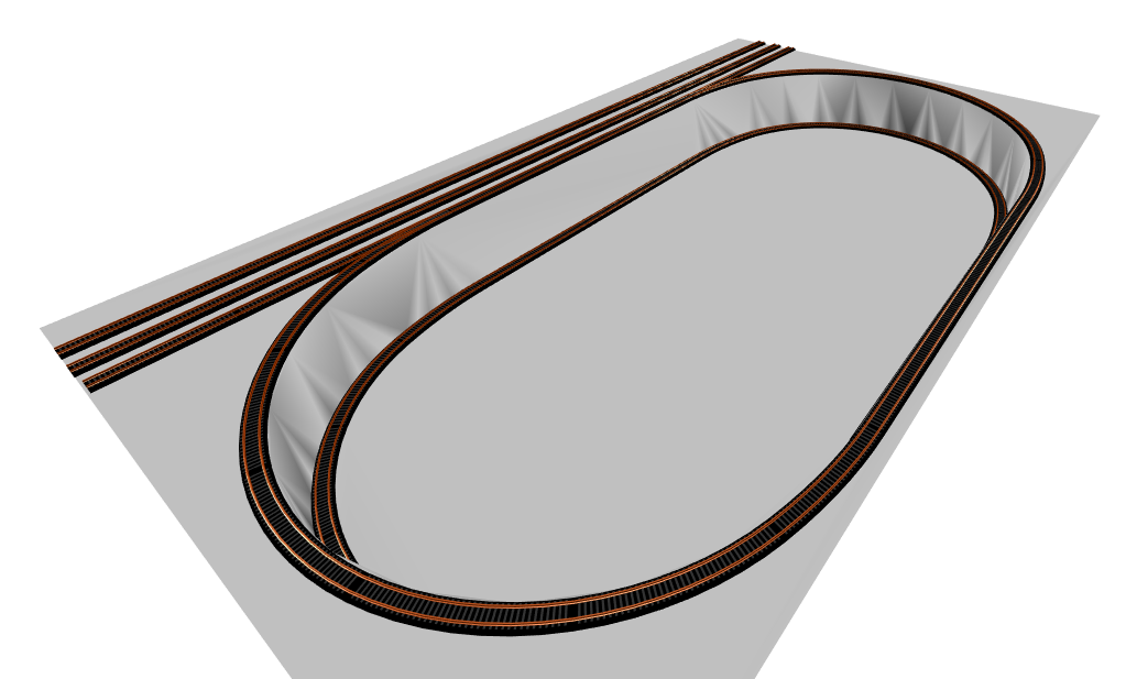
AnyRail 3D Track Layout (Angled View).
The top board was cut out along the inside of the track to provide both viewing and easy access to the bottom board. The bottom board, in turn, was cut along the outside of the bottom track with enough room to allow for structural support. Six wooden dowels are used to connect the short ends of the boards, while a wooden block with a width equivalent to the height of the dowels is screwed in place along the long end of the boards to provide additional support between the two. This plank was added only to the back end of the track, as the space at the bottom of the loops is best left clear so that observers can see the synchronization from in front. The back of the block is also used to run the wiring between the top and bottom boards for clean presentation.
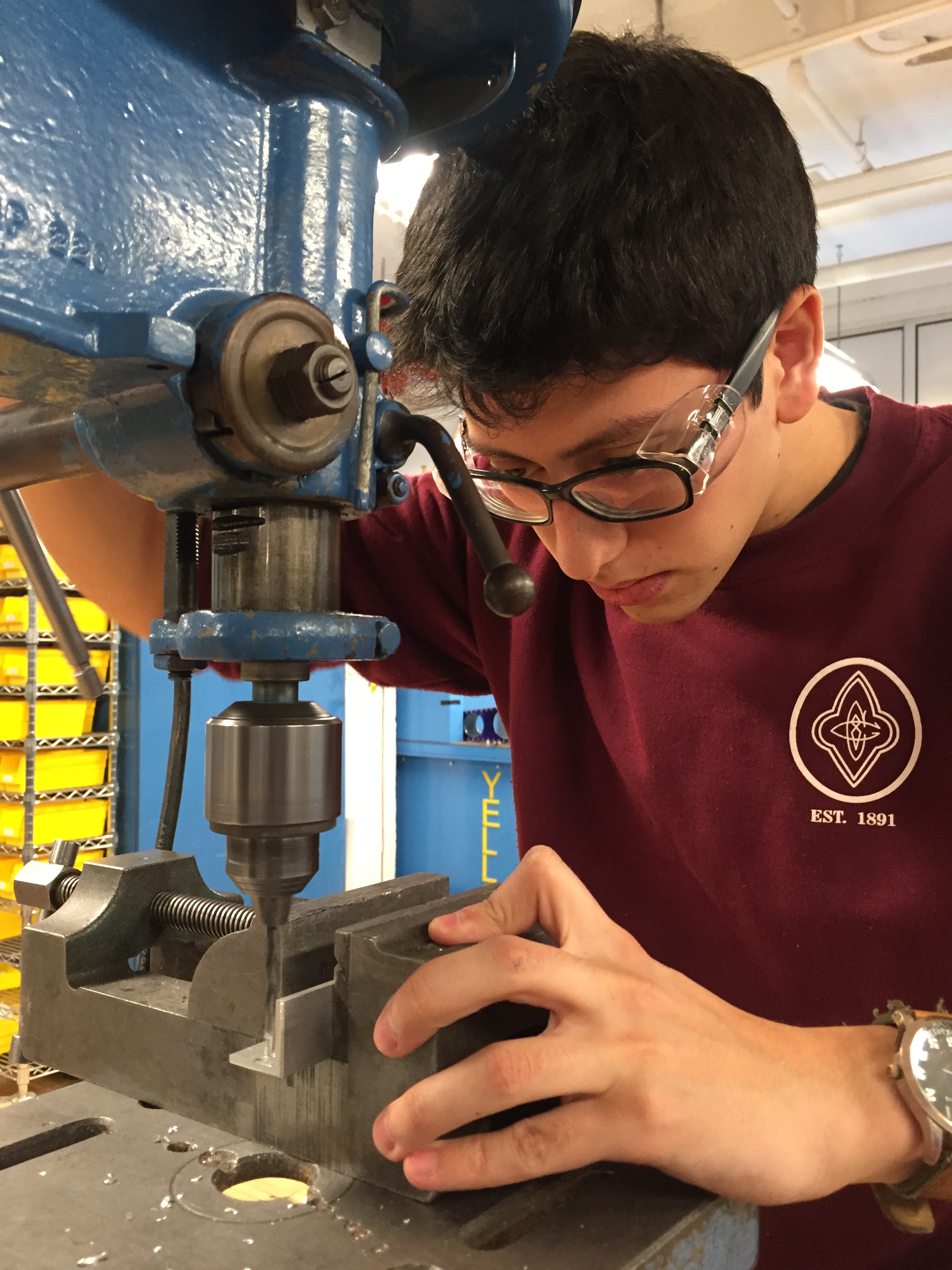
This was when I was making metal supports for the bottom board from scrap metal I cut with a band saw. We could have added them easily but decided that the structure was fine with only the wooden supports and much more aesthetically pleasing.

This image was taken while assembling our board.
Control Design
This was my favorite part of the project! (I apologize if this part is a little long.) The purpose of the project was to synchronize the two trains but this was a challenge because each track only had 3 hall effect sensors each. The hall effect sensors have an open collector so they are default high signal thanks to a pull-up and are pulled low when a magnetic field is presented near the sensor.
By placing a small magnet under a train and hall effect sensors below the track, a low signal is sent when the train is directly above the sensor. Both the AC train track and the DC train track have three hall effect sensors. On each of the two tracks, there are two sensors across a 40cm distance tied together so when a train passes over either of these two ”distance” sensors, their signal is pulled low. The third sensor on each track, also known as the clear sensor, is used as a checkpoint to make sure that no errors occurred and to label a new lap.
We could have finished our control system there but we wanted to build a robust control system that would function even if a sensor somehow didn't work properly when a train passed over it. To solve this, I turned to my computer science course that I took in my underclassman years and created a turing machine to account for mistakes in the sensors.
The tracks were each divided by the three hall effect sensors into the three sections that determined the general locations of the trains. To keep track of these three sections, two bits were assigned to describe each section of the track. As a train passed over a sensor and entered a new section the stored bits were reassigned to match the next section.
With the use of the Turing machine method, the detection of errors and resetting them for continuous code became very smooth with the use of only two bits of information. This method also allowed for the initial state of the train to occur anywhere on the track because the code could reliably determine the location of the trains in one lap. Lastly, the method allowed for custom code to measure different timing variables without the worry that the order of the triggering of the sensors would cause an uncorrectable error.
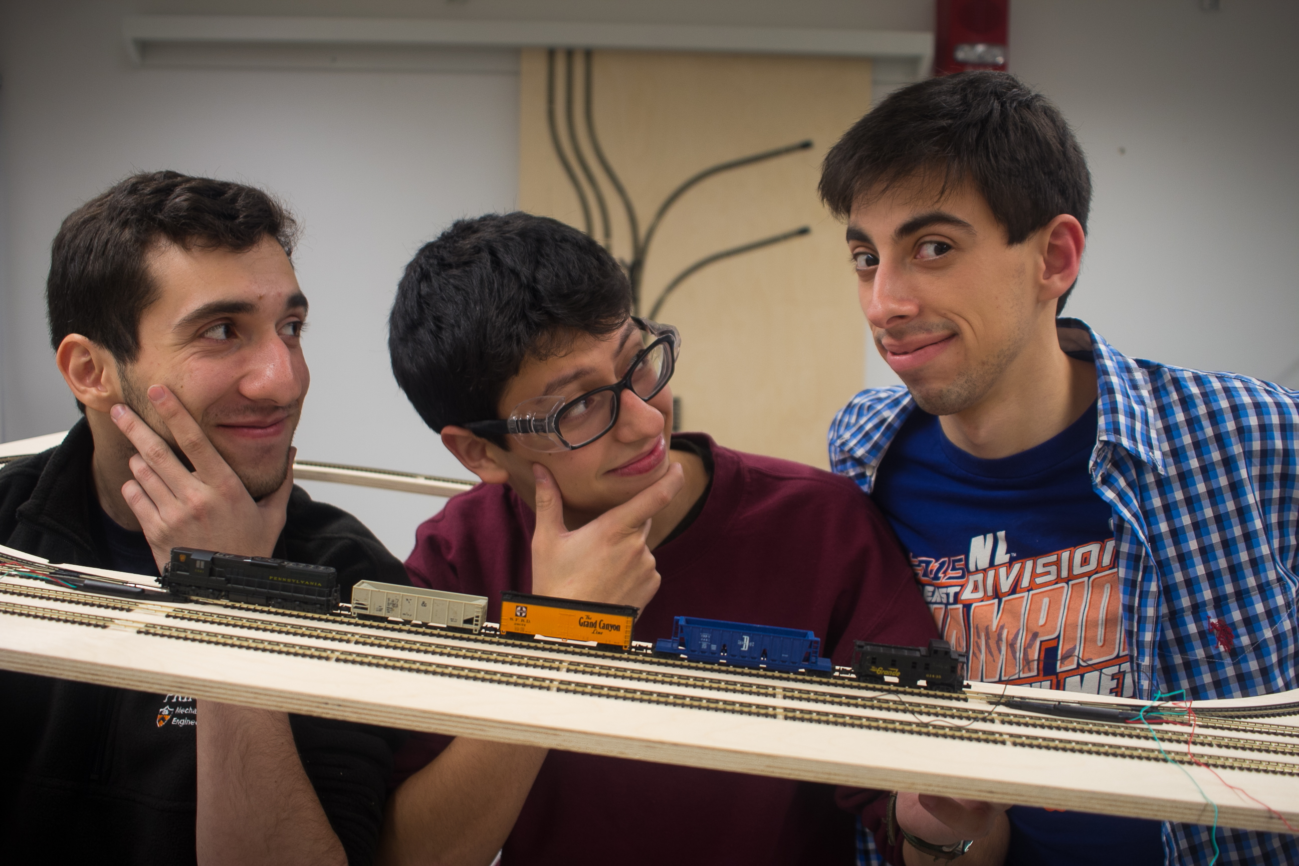
An of image three brave engineers (Daniel Echeverri, William Guiracoche, and Joshua Umansky) who were just getting into their work. Little did they know that over the next three weeks they would get less than 3 hours of sleep every day and sometimes sleep under the table in the microprocessors lab with only their growing facial hair to keep them warm.